Why These Two Defects Are So Often Misidentified in Practice
In real foundry practice, shrinkage cavities and shrinkage porosity are rarely isolated, textbook-perfect defects. They often appear in similar locations, under similar solidification conditions, and sometimes even within the same casting. This is the main reason why these two defects are frequently misidentified—especially outside of laboratory conditions.
1. They Originate From the Same Solidification Problem
Both defects are fundamentally linked to insufficient feeding during solidification. The difference lies in how the metal fails to compensate for volumetric shrinkage:
- Shrinkage cavities form when there is a complete loss of feeding in a localized hot spot.
- Shrinkage porosity develops when feeding is partially restricted, causing numerous small voids instead of one large cavity.
Because the root cause overlaps, many foundry teams initially assume the defects are the same and apply identical corrective actions—often with poor results.
2. They Frequently Appear in the Same Critical Zones
In production castings, both defects tend to occur in:
- Thermal centers
- Thick sections connected to thinner walls
- Areas far from effective risers or chills
When defects are discovered in these regions, inspectors often rely on location alone for identification. This leads to misjudgment, because location is a clue, not a diagnosis.
3. Machining Often Reveals the Defect Too Late
Another common source of confusion is that many shrinkage-related defects are not visible in the as-cast condition.
- A casting may pass visual inspection and basic NDT.
- The defect only becomes obvious after machining, when internal voids break through the surface.
At this stage, the defect morphology may appear ambiguous:
- A large cavity may look like clustered porosity.
- Distributed porosity may be mistaken for a single feeding failure.
By the time the defect is exposed, the opportunity to accurately observe its original formation has already been lost.
4. Radiographic and Ultrasonic Results Can Look Similar
Non-destructive testing is essential, but it does not automatically solve the identification problem.
- Radiographic testing (RT) may show both defects as dark, irregular indications with unclear boundaries.
- Ultrasonic testing (UT) can display scattered signal loss that is difficult to classify without experience.
Without correlating NDT results to solidification behavior and casting geometry, even experienced inspectors can draw incorrect conclusions.
5. Experience Gap Is a Major Factor
In many foundries, defect classification is performed by:
- Junior engineers
- General quality inspectors
- Buyers reviewing third-party inspection reports
These roles often lack long-term exposure to process-side decision making. As a result, defects are labeled based on appearance alone rather than formation mechanism, which is the key to correct identification.
This experience gap is one of the most overlooked reasons why shrinkage cavities and shrinkage porosity continue to be confused in daily production.
Misidentifying these defects does not just affect terminology—it directly impacts process correction effectiveness, scrap and rework rates, and overall project cost and delivery timelines.
That is why distinguishing between shrinkage cavities and shrinkage porosity requires more than definitions. It requires understanding how the casting actually solidified.
What Happens If You Diagnose It Wrong? (Real Consequences)
In foundry operations, misidentifying shrinkage cavities and shrinkage porosity is not a minor terminology issue. It often leads to incorrect process corrections, repeated defects, and unnecessary cost increases. The two defects may look similar, but the consequences of treating them as the same can be significant.
1. Wrong Diagnosis Leads to the Wrong Fix
Each shrinkage-related defect requires a different corrective approach. When the diagnosis is wrong, the improvement action targets the symptom rather than the root cause.
| Misdiagnosis | Applied Correction | Actual Root Cause | Result in Production |
|---|---|---|---|
| Shrinkage cavity treated as porosity | Degassing, melt treatment, chemistry adjustment | Feeding path interruption | Defect remains or reappears |
| Shrinkage porosity treated as cavity | Additional risers or oversized feeders | Partial feeding with micro-void formation | Cost increases without quality improvement |
This is one of the most common reasons why corrective actions appear logical on paper but fail in actual production.
2. Scrap, Rework, and Machining Losses Increase
When the defect type is misunderstood, foundries often proceed with machining under the assumption that the problem has been solved.
- Machining exposes hidden voids.
- Finished parts are scrapped late in the process.
- Value-added operations are lost.
Late-stage scrap is especially damaging because it multiplies the cost impact of a single defect.
3. Production Stability Gets Worse, Not Better
Incorrect fixes can unintentionally introduce new variables into the process:
- Oversized risers may disturb solidification balance.
- Excessive chills may cause local cracking.
- Unnecessary melt treatments can increase variability.
As a result, defect frequency may fluctuate instead of improving, making the process harder to control over time.
4. Delivery Delays and Customer Complaints Follow
Repeated trial-and-error corrections often lead to:
- Extended production cycles
- Missed delivery deadlines
- Customer rejections or claims
From the customer’s perspective, the issue is no longer a single defect, but a loss of confidence in process control.
5. Buyers and Quality Engineers Lose Decision Clarity
For buyers and quality engineers reviewing inspection reports, misclassification creates confusion:
- Root cause analysis appears inconsistent.
- Corrective actions lack technical logic.
- Supplier credibility is questioned.
In many cases, the real issue is not capability, but incorrect defect identification at an early stage.
Understanding the consequences of misdiagnosis highlights an important principle: shrinkage cavities and shrinkage porosity must be distinguished by formation mechanism, not appearance alone.
Field-Level Identification: How to Tell the Difference Without Lab Tests
In real production environments, laboratory analysis is not always available or practical. Foundry engineers and quality teams often need to distinguish between shrinkage cavities and shrinkage porosity directly on the shop floor. The following identification methods are based on solidification behavior and field experience rather than idealized definitions.
1. Location Logic: Where the Defect Appears Matters
While location alone is not sufficient for diagnosis, it provides a strong first-level indicator when interpreted correctly.
- Shrinkage cavities are typically found at the final solidification point, often deep inside a thermal center or isolated hot spot with no effective feeding path.
- Shrinkage porosity tends to appear distributed within a hot zone, rather than concentrated at a single point.
If the defect consistently appears at the same isolated location across multiple castings, a shrinkage cavity is more likely. If it appears scattered throughout a section, shrinkage porosity should be suspected.
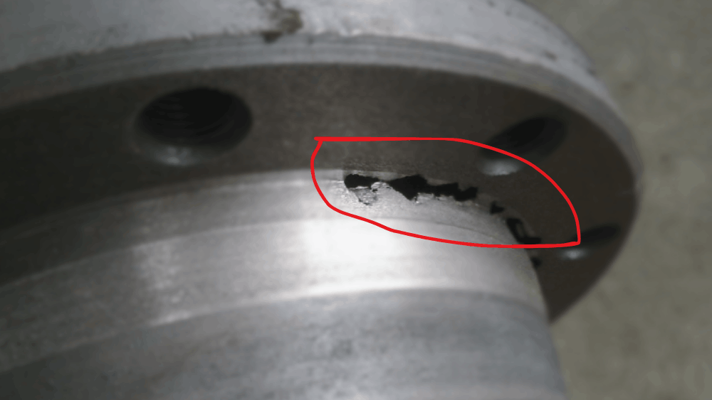
2. Shape and Exposure After Machining
Machining often provides the clearest opportunity for field-level identification. The way the defect reveals itself during material removal is highly diagnostic.
- Shrinkage cavities usually expose a single, irregular void with uneven edges and a relatively concentrated depth.
- Shrinkage porosity appears as multiple small voids that emerge progressively as machining continues.
If additional voids continue to appear after further machining passes, the defect is far more likely to be shrinkage porosity than a single cavity.
3. Surface Texture Inside the Defect
A close visual inspection of the internal surface provides additional clues.
- Cavities often show rough, torn-looking surfaces that reflect interrupted metal feeding.
- Porosity typically presents a sponge-like or honeycomb texture formed by interconnected micro-voids.
These textural differences are especially visible when defects are exposed by milling rather than drilling.
4. Consistency Across the Same Batch
Batch-to-batch and part-to-part consistency is a powerful diagnostic tool.
- A shrinkage cavity often appears sporadically, depending on local feeding effectiveness.
- Shrinkage porosity tends to show repeatable patterns across multiple parts produced under the same conditions.
When similar void patterns are observed in the same region of multiple castings, shrinkage porosity is the more likely cause.
5. Simple Sectioning as a Practical Confirmation Method
When uncertainty remains, controlled sectioning can provide clarity without full laboratory analysis.
- Sectioning through a cavity typically reveals a localized volume loss.
- Sectioning through shrinkage porosity reveals a network of fine voids extending through the affected zone.
This method is especially useful during trial production or root cause investigations.
Field-level identification does not require advanced equipment, but it does require linking visual evidence to solidification behavior. When this connection is made, shrinkage cavities and shrinkage porosity become far easier to distinguish in practice.
How Foundries Misread X-ray and Ultrasonic Testing Results
Non-destructive testing such as radiographic testing (RT) and ultrasonic testing (UT) plays a critical role in casting quality control. However, inspection results are often overinterpreted or misinterpreted when they are not linked to solidification behavior and casting design. This is one of the main reasons shrinkage cavities and shrinkage porosity are frequently confused.
1. Why Radiographic Images Can Be Misleading
Radiographic testing displays internal density variations as two-dimensional images. While effective for detecting voids, it does not directly reveal how those voids formed.
- Shrinkage cavities may appear smaller than their actual volume due to projection angle and overlapping dense regions.
- Shrinkage porosity often shows as diffuse, cloud-like dark areas that lack clear boundaries.
Because both defects reduce local density, radiographic images alone cannot reliably distinguish between a single feeding failure and distributed micro-void formation.
2. Limitations of Ultrasonic Testing for Shrinkage Defects
Ultrasonic testing detects internal discontinuities based on sound wave reflection. It is highly sensitive, but interpretation requires experience.
- Large shrinkage cavities usually produce strong, isolated signal reflections.
- Shrinkage porosity often causes scattered signal attenuation that may be mistaken for background noise.
In practice, porosity-related signals are sometimes underestimated or dismissed, leading to incomplete defect classification.
3. Inspection Results Without Process Context
A common mistake in quality evaluation is reviewing RT or UT reports in isolation.
- Inspection teams focus on indication size, not formation mechanism.
- Engineering teams focus on process changes without reviewing NDT patterns.
When inspection data is separated from casting geometry, feeding design, and solidification sequence, the likelihood of misdiagnosis increases significantly.
4. Why Similar Indications Can Mean Different Things
Two defects with similar NDT indications may originate from entirely different causes.
- A single dark region in RT could indicate a localized shrinkage cavity or overlapping porosity clusters.
- Weak UT signals may result from surface roughness, geometry interference, or genuine shrinkage porosity.
Without correlating inspection findings to actual casting behavior, corrective actions are often based on assumptions rather than evidence.
5. Best Practice: Combine NDT With Solidification Analysis
Effective defect identification requires combining inspection results with process knowledge:
- Review feeding paths and riser effectiveness.
- Analyze section thickness transitions.
- Compare defect locations across multiple castings.
When NDT data is interpreted alongside solidification behavior, the distinction between shrinkage cavities and shrinkage porosity becomes much clearer.
Non-destructive testing is a powerful tool, but it should be viewed as a diagnostic aid rather than a final verdict. True defect identification requires understanding how the casting actually solidified.
Root Causes: Stop Using the Same Fix for Both Defects
Although shrinkage cavities and shrinkage porosity are related to solidification shrinkage, they do not respond to the same corrective actions. Treating them with identical solutions is one of the most common and costly mistakes in casting improvement efforts.
1. When the Defect Is a Shrinkage Cavity
A shrinkage cavity indicates a complete breakdown in feeding at a specific location during the final stage of solidification. The corrective focus must therefore be on restoring an effective feeding path.
- Riser size, placement, and feeding efficiency
- Solidification sequence and directional solidification
- Hot spot isolation caused by geometry or mold design
Simply improving melt quality or degassing will not eliminate a shrinkage cavity if the metal has no physical path to compensate for volumetric contraction.
2. When the Defect Is Shrinkage Porosity
Shrinkage porosity forms when feeding is partially restricted, allowing micro-voids to develop throughout a hot zone rather than at a single point.
- Local solidification rate control
- Alloy composition and freezing range
- Interaction between feeding resistance and interdendritic shrinkage
In this case, adding oversized risers alone may increase cost without significantly reducing porosity levels.
3. Decision Path: How to Choose the Right Corrective Direction
Instead of applying multiple changes simultaneously, foundries should follow a structured decision path:
- If the defect is localized and isolated → focus on feeding design.
- If the defect is distributed and repeatable → focus on solidification control.
- If defect behavior changes with section thickness → review geometry transitions.
This approach reduces trial-and-error and leads to faster, more reliable improvements.
4. Why Overcorrecting Often Makes Things Worse
Applying aggressive corrective measures without proper diagnosis can introduce new problems:
- Excessive risers increase yield loss.
- Strong chills may cause cracking or residual stress.
- Multiple simultaneous changes mask the true root cause.
Overcorrection may temporarily shift defect location but rarely eliminates the underlying problem.
Effective defect reduction depends on understanding how feeding actually failed, not just on increasing process complexity.
A Practical Checklist for Buyers and Quality Engineers
For buyers, quality engineers, and project managers, the goal is not to become defect specialists, but to ask the right questions and recognize warning signs early. The following checklist helps bridge the gap between inspection results and practical decision-making.
1. Defect Location and Repeatability
- Does the defect appear at a single, consistent hot spot?
- Or is it distributed across a wider section?
- Does the same pattern repeat across multiple castings in the batch?
Localized and inconsistent defects often point to shrinkage cavities, while repeatable, distributed defects suggest shrinkage porosity.
2. Behavior After Machining
- Does one large void appear suddenly during machining?
- Or do multiple small voids continue to appear as material is removed?
Machining behavior provides one of the most reliable practical indicators when laboratory analysis is not available.
3. Consistency Between NDT Results and Casting Geometry
- Do RT or UT indications align with thermal centers and feeding paths?
- Are inspection results reviewed together with casting drawings?
Inspection data should never be evaluated without considering geometry, solidification sequence, and riser effectiveness.
4. Logic Behind the Proposed Corrective Action
- Is the supplier proposing changes to feeding design or melt treatment?
- Can they clearly explain why that change addresses this specific defect?
Final Thoughts: Distinguishing Defects by Mechanism, Not Appearance
Shrinkage cavities and shrinkage porosity are often discussed as similar defects, but in real casting practice, their formation mechanisms, risks, and corrective actions are fundamentally different. Relying solely on visual appearance or inspection indications is one of the main reasons these defects continue to be misdiagnosed.
As this article has shown, accurate identification depends on understanding:
- How and where solidification feeding failed
- Whether the defect is localized or distributed
- How the defect behaves during machining and across batches
- How inspection results align with casting geometry and process design
When defects are classified based on formation behavior rather than surface appearance, corrective actions become more focused, more effective, and far less costly. This approach reduces trial-and-error, improves production stability, and builds long-term confidence between foundries and customers.


